Wiring a Emerson Control Techniques Commander SK to a three phase Bridgeport mill
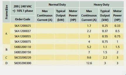
In order to power my three phase bridgeport mill from 1 phase 220V power I decided to install a VFD. I chose the Emerson Commander SK because of it's power and flexibility. With a 220V 1 phase input you can go up to 3HP. My mill is only 1 HP and an easy fit.
I decided to control my mill with the existing barrel switch plus a potentiometer for speed adjustment. I purchased a 10K bourns potentiometer. This one has 10 turns from 0 to 100%. It also has a dial which shows it's position between 1-10. I used a piece of Cat6 cable and soldered the pot in. The cat6 is 23 AWG with the added benefit of a plastic spine to keep the wire rigid.

The potentiometer has 3 tabs. Ground, power and the output. With a voltage applied you'll see a variable voltage output to translate to the adjustable speed.

At the motor I disconnect the barrel switch and directly connect the motor.

I used a screw to connect the terminals and covered in heat shrink tubing.

Next I used 3 other conductors from the cat6 to connect to the switch. Notice the soldered wires that reverse the 3 phase motor. the front phase reverse connects to the forward while the other two swap. reverse of phase 2 connects to forward of phase 3. When wiring your motor into the VFD, if it goes the wrong direction, you just switch two of the wires to reverse direction.

Programming and testing
First I followed the quick starting instructions which have you use the control pad for on/off and speed control.
I purchased a USB to RS485 adapter on ebay for $5 to allow me to connect the drive to the free software CTsoft.

From the manual I find that the Pin 2 goes to A on my adapter. From the RS485 spec, A is the same as '-' also the same as TxD-/RxD- as well as called the inverting pin.
Pin 3 goes to GND
Pin 7 goes to B. B is also '+', TxD+/RxD+ and the non-inverting pin.

With CTsoft connected to the drive I can to an autotune, run through the initial installation wizard, etc.
After trying several configurations I talked to the folks at Emerson and got the expert opinion on the installation.
They had me wire the pot to T1, T2, T3. Thats GND, Output, 10V. This give my analog speed input.
The switch is wired to B2, B5, B6. Which is 24V, forward, reverse. In addition I had to put a jumper between B2 and B4. This is the enable switch and should be wired to an emergency stop switch.

The parameters I changed were:
Parameter Description
00.01 Minimum set speed 0.0 Hz
00.02 Maximum set speed 60.0 Hz
00.03 Acceleration rate 1 33.0 s/100 Hz
00.04 Deceleration rate 1 11.0 s/100 Hz
00.05 Drive configuration AV.Pr
00.06 Motor rated current 3.30 A
00.07 Motor rated full load rpm 1730 RPM
00.08 Motor rated voltage 230 V
00.09 Motor rated power factor 0.75 - this came from the autotune
00.10 Security status L3
00.11 Start / stop logic select 0
00.41 Voltage mode select UrA

Comments