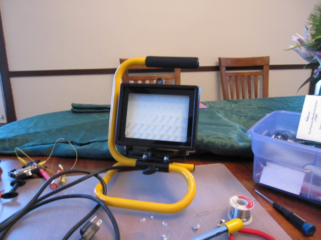
I decided to try a harbor freight LED worklight. Unfortunately they aren't very bright. I figured I might as well fix that by re-engineering it.
This is a comparison of the new LED with the old. I got the new LED's on ebay. They are .5W 5mm LED's
- Emitting Colour: 5mm 60° 5-Chips 0.5 Watt High Power WHITE LED
- LENS Type:Water clear
- Color Temperature: 8000K
- Luminous Intensity-MCD: Min: 90,000mcd Max: 130,000 mcd
- Reverse Voltage:5.0 V
- DC Forward Voltage: Typical: 3.4 V Max: 3.6V
- DC Forward Current:100mA
- Viewing Angle:60 degree


 They use an interesting circuit that uses a bridge rectifier to change AC to DC. They use a capacitor to limit the AC current.
I got a great description of the circuit from http://www.electro-tech-online.com
R1, R2 and C1 limit the current. The idea is that C1 limits the current, and it does so without getting hot.
R1 is only there to discharge C1 when the whole circuit is disconnected from the mains, for safety. It is large so little current goes though it and adds nearly nothing to the current in the LEDs
R2 is there to limit the C1 charging current when the circuit is connected to the mains. It is small enough to make virtually no difference to the current in the LEDs
C2 is there to smooth the current in the LEDs so that they don't flicker.
The nice think about this is you are using the full 120 volts to drive the LED's.
Originally C1 was .68uF and allowed about 10ma of current to the LED's
V/I =R Since I know I need about 80V at 100mA. 118V is about the AC line input.
R= (118-80)/.1 = 380 Ohms
From the Capacitive Reactance equation
C = 1/(2*pi*f*Xc) = 1/(2*3.14*60*380) =6.98uF
V/I =R Since I know I need about 80V at 100mA. 118V is about the AC line input.
R= (118-80)/.1 = 380 Ohms
From the Capacitive Reactance equation
C = 1/(2*pi*f*Xc) = 1/(2*3.14*60*380) =6.98uF
I first tried increasing C1 to 8uF, but found that that allowed too much current to flow (200ma) to the LED's. With this high of current the wattage of the resistor would have to be 10W to limit the LED current on the DC side.
While doing some more reading I figured voltages on there do not add arithmetically to voltages across resistors or LEDs.
Also I learned, the average rectified current is about 1.11 times the RMS current, so you want about 90 mA RMS
The phases will be at 90º, so the voltage after a drop of 380 Ω * 90 mA = 34.2V is
sqrt(120² - 34.2²) = 115 V
Next I will try a 2.2uF Capacitor for c1.
After a few weeks for digi-key to complete my order I install the 2.2uF capacitor. Unfortunately the output is not enough. The voltage output to the LED's is 56V and 50mA.
Back to the drawing board.
I guess next I'll try a 4uF Cap and measure the output.
With a 4uF Capacitor, I measure 61V and 106mA. Perfect. I through in a 5 Watt 100 ohm resistor (R2) for good measure.

As you can see it is now useful enough to light up a room by itself.
This is the original circuit.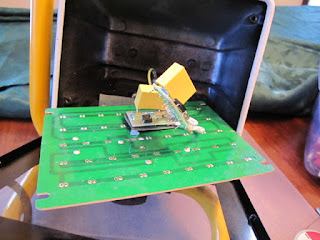

This is with the 8uF capacitor over driving the LED's at 200ma

Comments